Sources: brief Biddle comments in Heat Transfer (36); related U/UA from (07), (29), (30); textbook Chapter 11 (11.1–11.4) as primary support. No worked examples included.
1. Overview
A heat exchanger moves heat from a hot fluid to a cold fluid through a separating wall: hot-fluid convection → wall conduction → cold-fluid convection. This is why Ch. 11 leans on the U/UA ideas from Chapters 3 and 8.
Two analysis methods:
- LMTD — terminal (inlet/outlet) temperatures known or found from energy balances.
- Effectiveness–NTU — outlet temperatures unknown but size/UA known.
Parallel flow: fluids enter the same end, same direction. Counterflow: fluids enter opposite ends. Counterflow is generally more effective because the fluid-to-fluid ΔT stays more uniform along the length. Because that ΔT varies along the exchanger, the driving difference is the log-mean ΔTlm, not an arithmetic average.
2. Governing Equations
2.1 Energy balances & heat capacity rate
With negligible loss to surroundings, heat lost by the hot fluid = heat gained by the cold fluid:
q˙=m˙hcp,h(Th,i−Th,o)=m˙ccp,c(Tc,o−Tc,i)
Heat capacity rate C=m˙cp, [C]=W/K, so Ch=m˙hcp,h, Cc=m˙ccp,c:
q˙=Ch(Th,i−Th,o)=Cc(Tc,o−Tc,i)
The fluid with the smaller C changes temperature more for the same q˙.
2.2 Rate equation & overall coefficient U
q˙=UAΔT
Series resistances for a tube wall (with fouling):
UA1=hiAi1+Rf,i+2πkLln(ro/ri)+Rf,o+hoAo1
Neglecting fouling:
UA1=hiAi1+2πkLln(ro/ri)+hoAo1
U depends on the reference area, but UA is unique:
UA1=UiAi1=UoAo1,Ai=πDiL,Ao=πDoL
With finned surfaces, use the overall surface (temperature) efficiency ηo:
UA1=(ηohA)h1+(ηoA)hRf,h′′+Rw+(ηoA)cRf,c′′+(ηohA)c1
Rw = wall conduction resistance; subscripts h,c = hot/cold sides (ηo from Ch. 3.6.4).
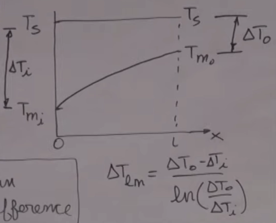
2.3 Log-mean temperature difference (LMTD)
ΔTlm=ln(ΔT1/ΔT2)ΔT1−ΔT2
If ΔT1=ΔT2 then ΔTlm=ΔT1=ΔT2. End differences depend on arrangement:
- Parallel: ΔT1=Th,i−Tc,i, ΔT2=Th,o−Tc,o
- Counterflow: ΔT1=Th,i−Tc,o, ΔT2=Th,o−Tc,i (the reference ΔTlm,CF)
2.4 LMTD method & correction factor F
q˙=UAΔTlm
For multipass / shell-and-tube / crossflow, correct the counterflow LMTD:
q˙=UAFΔTlm,CF
F=1 for ideal double-pipe parallel and counterflow. Otherwise read F=f(P,R) from the textbook charts, with t = tube-side, T = shell-side fluid:
R=to−tiTi−To,P=Ti−tito−ti
2.5 Effectiveness–NTU (core)
ε=q˙maxq˙,q˙max=Cmin(Th,i−Tc,i),Cmin=min(Ch,Cc)
q˙=εCmin(Th,i−Tc,i)
NTU=CminUA,Cr=CmaxCmin,Cmax=max(Ch,Cc)
For every arrangement ε=f(NTU,Cr) — specific relations in §3.
Quick lookup — full ε-NTU relations follow in §3.1–3.5 (end differences for ΔTlm are in §2.3):
| Type | Key feature | Rate form | F |
|---|
| Double-pipe parallel flow | fluids enter same end, same direction | q˙=UAΔTlm | F=1 |
| Double-pipe counterflow | fluids enter opposite ends | q˙=UAΔTlm,CF | F=1 (reference) |
| Shell-and-tube | one fluid in tubes, one in shell; baffles induce shell-side crossflow | q˙=UAFΔTlm,CF | chart (P,R) |
| Crossflow (single pass) | fluids cross ≈ perpendicular; mixed/unmixed behavior matters | q˙=UAFΔTlm,CF | chart (P,R) |
| Compact exchanger | large area density (>700 m²/m³), small passages, often gas-side controlling | q˙=UAΔTlm (via its arrangement) | per arrangement |
3.1 Double-pipe parallel flow
ε=1+Cr1−e−NTU(1+Cr)(11.28a)
3.2 Double-pipe counterflow
ε=1−Cre−NTU(1−Cr)1−e−NTU(1−Cr)(Cr<1, 11.29a)
ε=1+NTUNTU(Cr=1)
3.3 Shell-and-tube
One shell pass (2, 4, … tube passes):
ε1=2{1+Cr+(1+Cr2)1/21−e−(NTU)1(1+Cr2)1/21+e−(NTU)1(1+Cr2)1/2}−1(11.30a)
n shell passes (2n, 4n, … tube passes):
ε=[(1−ε11−ε1Cr)n−1][(1−ε11−ε1Cr)n−Cr]−1(11.31a)
Correction factor: R=to−tiTi−To, P=Ti−tito−ti; read F from Fig. 11.10 (1 shell, 2/4/… tube passes).
3.4 Crossflow (single pass)
Both fluids unmixed:
ε=1−exp[Cr1(NTU)0.22(e−Cr(NTU)0.78−1)](11.32)
Cmax mixed, Cmin unmixed:
ε=Cr1(1−e−Cr[1−e−NTU])(11.33a)
Cmin mixed, Cmax unmixed:
ε=1−e−Cr−1[1−e−CrNTU](11.34a)
3.5 Compact exchanger
No distinct relation — analyze with the relation for its actual flow arrangement (usually crossflow).
Any type with Cr=0 (one fluid boiling/condensing, C→∞):
ε=1−exp(−NTU)(11.35a)
4. Solution Workflows
4.1 LMTD — terminal temperatures known
- Identify exchanger type / flow arrangement.
- Compute Ch, Cc.
- Energy balances → missing outlet temperature or q˙.
- Get ΔT1, ΔT2 for the arrangement.
- Compute ΔTlm.
- Apply F if shell-and-tube/crossflow.
- q˙=UAFΔTlm → solve for q˙, A, or U.
4.2 Effectiveness–NTU — outlets unknown, UA known
- Compute Ch, Cc, Cmin, Cmax, Cr.
- NTU=UA/Cmin.
- Pick the ε relation for the type (§3).
- Compute ε.
- q˙=εCmin(Th,i−Tc,i).
- Energy balances → outlet temperatures.
5. Quick Decision Rules
- Terminal temps known / easy from energy balance → LMTD. Outlets unknown with UA known → ε–NTU.
- Sizing A from known terminal temps → LMTD is direct. Predicting outlets of an existing exchanger → ε–NTU is direct.
- Smaller C changes temperature more; Cmin sets q˙max=Cmin(Th,i−Tc,i).
- Double-pipe parallel/counter → F=1. Shell-and-tube or crossflow → use F chart, q˙=UAFΔTlm.
6. Key Takeaways
- HEs transfer heat between two fluids; apply energy balances on each.
- U bundles convection + wall conduction (+ fouling, + fin efficiency); UA is the overall conductance and is independent of area basis.
- LMTD handles the along-length variation of ΔT; use when terminal temps are known.
- ε–NTU when outlets are unknown; Cmin limits q˙max.
- Counterflow is generally more effective than parallel flow.
- Correction factor F is needed for most shell-and-tube and crossflow configurations.