Chapter 4: Static Body Stresses
Source files used: Hibbeler, Statics and Mechanics of Materials, Chapter 14 (Sections 14.1 to 14.5, stress transformation derivations); textbook Chapter 4 (Fundamentals of Machine Component Design). No worked examples are included.
1. Big Picture
Chapter 4 finds the stresses inside a part under static loads.
Chapter 2 asked: what external loads act on the member? Chapter 4 asks: what stresses do those loads create inside the member, and where are they highest?
The chapter introduces:
- nominal stress formulas for axial, direct shear, torsion, bending, and transverse shear loads,
- the conditions under which those formulas give the true maximum,
- the curved-beam correction,
- stress transformation, principal stresses, and Mohr’s circle,
- three-dimensional Mohr circles and the absolute maximum shear stress,
- stress concentration, residual stress, and thermal stress.
These are body stresses under static load. Impact, fatigue, and surface stresses come in Chapters 7, 8, and 9.
The textbook states the transformation results and refers to strength of materials texts for the proofs. This guide takes the derivations from Hibbeler Sections 14.1 to 14.5.
2. Core Ideas
2.1 Average Stress Is Not Maximum Stress
always gives the average stress on a section. It gives the maximum stress only if the load is uniformly distributed. That needs all of these:
- the section is well away from the loaded ends (about three diameters from the end fittings),
- the load acts exactly along the centroidal axis (an eccentricity adds a moment ),
- the bar is a perfect straight cylinder with no holes, notches, threads, or scratches,
- the bar is free of residual stress,
- the bar stays stable (a long bar in compression can buckle),
- the bar is homogeneous.
Redundant load paths share load by stiffness, and the stiffer path carries more. In the textbook’s T-bracket on six welds (Figure 4.2), the two welds on the stiff paths can carry nearly all of a 600 N load instead of 100 N each. In a composite, the material with the higher carries the higher stress.
Notation: the textbook reserves for strength (, , ) and uses and for stress.
2.2 Plane Stress at a Point
Most loadings are coplanar, and a free surface carries no stress. So the surface element usually sees only , , and . This is plane stress (Hibbeler Section 14.1).
An element rotated by at the same point carries different components: , , . The state of stress is the same. Only its description changes. Equilibrium of a wedge cut from the element links the two descriptions (derived in subsection 3.9).
Two orientations matter for design:
- principal planes: zero shear, extreme normal stresses and ,
- maximum shear planes: from the principal planes, with acting on them.
2.3 Shear Sign Conventions: Textbook vs Hibbeler
The two books use different shear sign rules.
Textbook (Section 4.4):
- shear is positive if it tends to rotate the element clockwise,
- Mohr’s circle has the axis positive up,
- the principal angle (Eq. 4.17) is positive clockwise.
Hibbeler (Section 14.2):
- is positive if it acts in on the face,
- Mohr’s circle has the axis positive down, with reference point ,
- is positive counterclockwise.
A positive Hibbeler turns the element counterclockwise through the faces, and Hibbeler plots it downward. So both books plot clockwise shear up and draw the same circle. One rule covers both: plot clockwise shear up, and rotate on the circle in the same direction as on the element.
Hibbeler warns that his sign convention with a axis drawn positive up reverses the direction of . Do not mix the two books inside one problem. Positive and negative shear are physically the same kind of loading, so any convention works if it is used consistently.
2.4 Induced Stresses
Pure tension induces shear, and pure shear induces tension and compression (textbook Section 4.8). In some cases the induced stresses do more damage than the direct ones.
- Uniaxial tension : the maximum shear acts on planes at , with a normal stress on those planes.
- Pure shear (torsion): principal stresses and act on planes at , with zero shear on them.
2.5 Always Think in Three Dimensions
Every real stress state has three principal stresses. A uniaxial state has two zero principal stresses. A biaxial (plane) state has one.
Forgetting the zero principal stress can give a that is too low. The standard case is a pressurized cylinder. The tangential and axial stresses are both tensile, and the free outer surface gives a radial principal stress of zero. At the inner surface, the radial principal stress is , not zero.
Mohr called the largest of the three circles the principal circle. It gives and both extreme normal stresses.
2.6 Stress Concentration
Holes, notches, fillets, grooves, threads, and scratches raise the local stress above the nominal value. The theoretical factor assumes an ideal elastic, homogeneous, isotropic material. It depends only on shape (dimensionless ratios) and on the load type. Axial, bending, and torsion factors are different.
For static loads on ductile materials, the textbook ignores . Local yielding at the notch root redistributes the stress. A notched bar with starts to yield at half the load, but gross yielding still needs the full , the same as an unnotched bar.
matters for:
- brittle, relatively homogeneous materials,
- normally ductile materials that behave in a brittle manner under special conditions,
- fatigue and impact loading (Chapters 7 and 8).
Gray cast iron is the exception in the other direction. Its internal discontinuities already concentrate stress, so geometric stress raisers add little.
2.7 Residual and Thermal Stresses
Residual stresses remain when part of a section yields and the load is removed. Load removal is elastic, so the residual stress is the load stress minus the elastic stress for the same load:
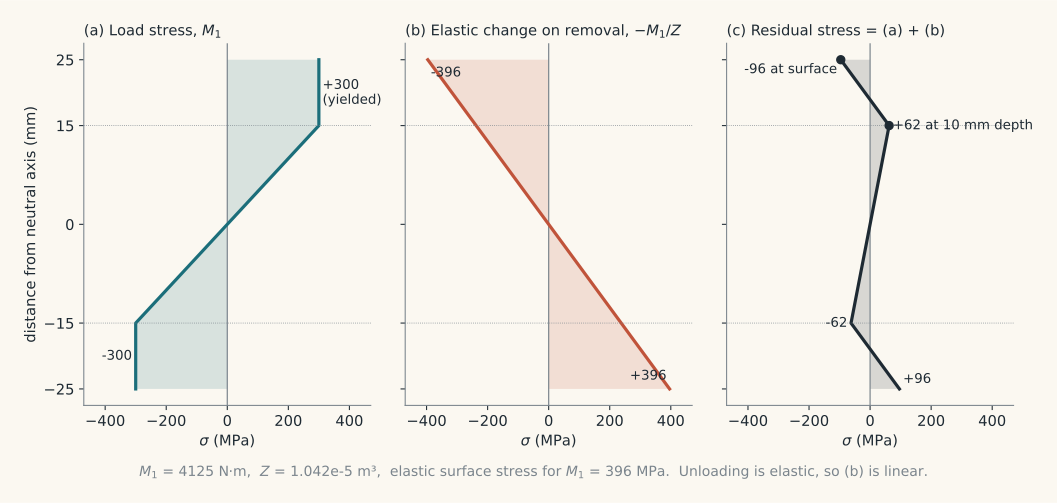
The textbook’s rule: an overload that yields the part leaves residual stresses that help later loads in the same direction and hurt loads in the opposite direction. With the idealized stress-strain curve, the gain in one direction equals the loss in the other.
Thermal gradients and phase changes also leave residual stress. The rule is “what cools last is in tension”:
- quenching puts the surface in residual compression and the core in triaxial tension,
- flame cutting and most welding leave the surface in residual tension,
- through-hardening steel to martensite leaves surface tension, unless special processing makes the skin transform last.
Annealing removes residual stress. Machining a part with residual stress upsets its internal equilibrium, so the part warps.
3. Main Governing Equations and Formulas
3.1 Axial Loading
Tension is positive, compression negative.
Use for the average normal stress on any section. It is the maximum only when all conditions in 2.1 hold.
3.2 Direct Shear
This is the average shear stress on the sheared area.
- Single shear (bolt in Figure 4.3): is one cross section.
- Double shear (hinge pin in Figure 4.4): is twice the pin cross section.
- Thread stripping: is the cylinder at the thread root, with height equal to the nut thickness. Standard threads have a little less area than a sharp “V” profile.
Direct shear is not pure shear, and the true maximum is above . Design uses this equation with conservative working stresses. For total shear fracture of a ductile part, set .
3.3 Torsion: Round and Rectangular Bars
For a straight round bar, solid or hollow:
Stress grows linearly from zero at the axis to a maximum at the outer surface. For a solid bar, :
For a hollow bar, use from Appendix B-1:
Valid only for a straight round bar with torque about its axis, a homogeneous elastic material, and a section away from load points and stress raisers.
For a rectangular bar (Figure 4.6), with the longer side and the shorter side:
The maximum is at the middle of the longer sides. Shear is zero along all edges. fails here because plane cross sections warp.
3.4 Straight Beam Bending
At the extreme fiber :
For a solid round bar, , , :
For a rectangle, .
Use for initially straight beams loaded in a plane of symmetry, with elastic homogeneous material, away from stress raisers and load points. For a section with one axis of symmetry, the neutral axis still passes through the centroid, so the larger stress is at the fiber farther from it.
3.5 Curved Beam: Derivation of the Stress Distribution
Assumptions: plane sections remain plane, elastic homogeneous material, load in the plane of curvature.
Notation (Figure 4.10):
- : radius to a fiber,
- : radius of the neutral axis,
- : radius of the centroidal axis,
- : shift of the neutral axis toward the center of curvature,
- : distance outward from the neutral axis, so ,
- : angle of the element, : rotation of the cut plane under .
Strain. A fiber at has length and stretches by :
Stress:
This is hyperbolic in , not linear.
Force equilibrium, :
Moment equilibrium, :
Split the integrand with . The second part integrates to zero by force equilibrium. The first part is , because is measured from the neutral axis and the centroid sits at :
Substitute into the stress equation:
Extreme fibers: put (so ) and (so ). With the textbook convention that a positive straightens the beam (Eq. 4.9):
where and are measured from the neutral axis.
Use for sharply curved members: hooks, C-clamps, press frames, chain links.
3.6 Curved Beam: Neutral Axis and Curvature Factors
Put into the force equilibrium condition:
This is Eq. 4.10. For a rectangle of width and depth , :
For other sections, evaluate the integral in closed form, numerically, or graphically.
Curvature factors compare the result with the straight-beam value (Eq. 4.11):
Here is measured from the centroidal axis. Figure 4.11 plots and for common sections against .
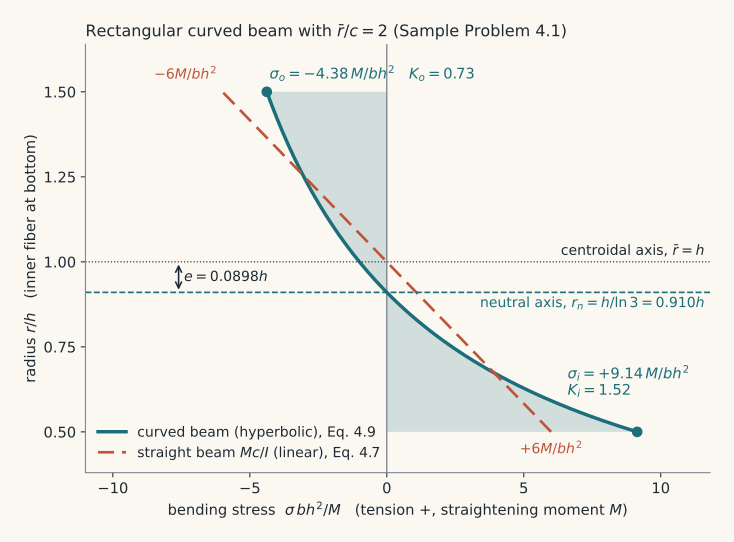
The inside surface is the shortest, stiffest path, so it carries more stress. Rule of thumb: if , the inner fiber stress is usually within 10 percent of .
Curved beams also carry radial stresses. They are small in heavy sections but can cause damage in thin-web I-beams, especially in brittle materials or under fatigue.
3.7 Transverse Shear in Beams: Derivation
Cut a beam segment of length from the top surface down to level (Figure 4.14). The bending moment on the right face is larger by , so the bending forces on the two faces do not balance. A shear force on the bottom face of the segment balances them:
With (Eq. 4.12):
where:
- : first moment of the area above the cut about the neutral axis (often written , giving ),
- : section width at the cut,
- : moment of inertia of the whole section.
Consequences:
- at the top and bottom surfaces, where the bending stress is largest,
- is normally largest at the neutral axis, where the bending stress is zero,
- a sudden drop in makes jump by the ratio of the widths,
- the equation assumes is uniform across .
A section much wider at the neutral axis than just above it can have its maximum away from the neutral axis. This is rare.
3.8 Transverse Shear: Maximum Values
Solid rectangle, , , :
At the neutral axis this gives Eq. 4.14:
Solid round, radius : the half disk above the neutral axis has first moment , with and . This gives Eq. 4.13:
Thin-walled round tube (Eq. 4.15):
I-beam: approximate the web shear by divided by the web area, with the web taken over the full beam depth.
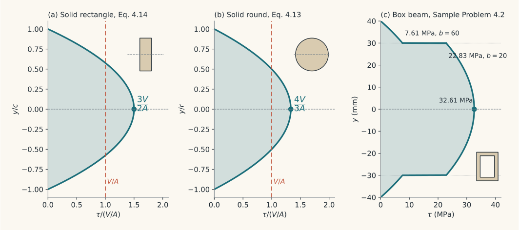
Use to check short beams. In long beams, bending stress dominates.
3.9 Plane Stress Transformation: Derivation
Hibbeler’s sign convention applies here: acts in on the face, and is measured counterclockwise from to the outward normal of the cut plane.
Cut the element along the inclined plane. If the inclined face has area , the vertical face has area and the horizontal face has area . Multiply each stress by its area to get forces.
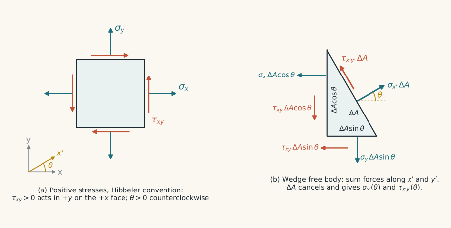
, with cancelling:
:
Use , , and (Hibbeler Eqs. 14-1 and 14-2):
For , replace with (Hibbeler Eq. 14-3):
So for every .
Use for the stresses on any plane through the point. A negative result acts in the or direction.
3.10 Principal Stresses: Derivation
Differentiate from 3.9:
The normal stress is extreme exactly where the shear stress is zero. Set the derivative to zero (Hibbeler Eq. 14-4):
The two roots are apart on the element. Substitute them back into (Hibbeler Eq. 14-5, textbook Eq. 4.16):
The textbook writes the angle in its own convention (Eq. 4.17), with clockwise shear positive:
A positive puts the principal axes clockwise from the and axes. Both the shear sign and the angle sign flip relative to Hibbeler, so both forms give the same physical plane.
Use to find the extreme normal stresses and their planes.
3.11 Maximum In-Plane Shear Stress: Derivation
Differentiate from 3.9 and set it to zero:
is the negative reciprocal of , so and . Substitute back (Hibbeler Eq. 14-7, textbook Eq. 4.18):
A normal stress also acts on these planes (Hibbeler Eq. 14-8):
This is only the in-plane value. Check 3.14 before calling it .
3.12 Mohr’s Circle: Derivation
Move to the left side of the equation (Hibbeler Eqs. 14-9 and 14-10):
Square both and add. Since , the angle drops out (Hibbeler Eqs. 14-11 and 14-12):
This is a circle with center and radius . Each point gives the normal and shear stress on one plane. The and faces are apart on the element and apart on the circle, so angles on the circle are .
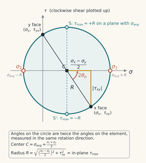
Read off:
Use for fast principal stresses and orientations, and to check results from 3.10 and 3.11.
3.13 Stresses on Any Plane from the Principal Stresses
With the angle measured from the #1 principal plane (textbook Eqs. 4.19 and 4.20):
These are the 3.9 equations with and along . The sign of follows the textbook’s clockwise rule. Hibbeler’s form has a minus sign.
Use when the principal stresses are already known.
3.14 Absolute Maximum Shear Stress
Order all three principal stresses by value, , including the zero one. The largest of the three Mohr circles gives:
The three principal shear stresses (textbook Section 4.11):
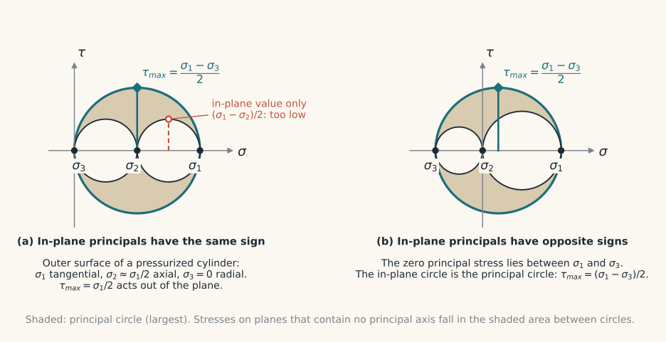
For plane stress with in-plane principal stresses and and a zero stress normal to the plane (Hibbeler Eqs. 14-13 and 14-14):
In the same-sign case, the maximum shear acts on planes inclined to the surface.
The 3D picture renames the stresses by value. In textbook Figure 4.33a, the in-plane ksi of Sample Problem 4.3 becomes point 3 and the zero stress becomes point 2.
Textbook answers that test this: Problem 4.62 (outer surface, 400 and 200 MPa) gives 200 MPa, not 100 MPa. Problem 4.67 (inner surface, 600 and 200 MPa at MPa) gives 350 MPa.
3.15 General Three-Dimensional Stress: Invariants
When shear acts on all faces, the principal stresses are the roots of the characteristic equation:
where:
The three real roots are . Then apply 3.14.
Work from these general forms. The printed steps of Sample Problem 4.4 contain typos (for example, where the data gives ).
3.16 Stress Concentration Factor
Each chart defines its own nominal stress, usually on the net section. For a stepped or grooved shaft, it uses the smaller diameter :
Read from Figures 4.35 to 4.41 with dimensionless ratios such as and . Use the chart for the correct load type.
For a notched bar of minimum area and an idealized elastic, perfectly plastic material:
Use only when 5.6 says it matters.
3.17 Residual Stress After Bending Overload
Replace the elastic-plastic stress block with resultant forces. is times the yielded area on one side, and is times the elastic triangle on one side. Then:
where and are the distances between the matching tension and compression resultants.
For a rectangle of width , half-depth , and elastic core half-depth , this becomes:
Removing is elastic:
Textbook values for the 25 by 50 mm steel beam with MPa yielded 10 mm deep:
- N·m, elastic surface stress MPa,
- residual stress MPa at the surface and MPa at 10 mm depth,
- elastic capacity afterwards: N·m in the same direction, N·m in the opposite direction.
Use for any overload that yields part of the section.
3.18 Thermal Strain and Restrained Thermal Stress
A free, uniform temperature change gives uniform expansion with no shear strain and no stress.
If the part is restrained, find the free expansion , subtract the movement the supports allow, and find the load that enforces the difference :
Then .
Valid only if the stress stays elastic at the operating temperature.
4. Problem-Solving Workflow
4.1 Finding the Critical Point Under Combined Loading
- Cut the member at the suspected critical section and draw the free body. List every internal load: , , , .
- Locate the peak of each stress: bending at the extreme fibers, torsion over the whole outer surface, transverse shear at the neutral axis, axial uniform.
- Pick the point where the large stresses overlap. For a round shaft in bending and torsion, it is the top or bottom surface point (points A and B in Figure 4.24).
- Compute each stress with 3.1 to 3.8.
- Transverse shear is zero at the extreme fibers and usually small. Neglect it there.
- Draw the element. Take the shear direction from the direction of twist, then use equilibrium for the other pair of faces.
- Find , , , and the in-plane (3.10 to 3.12).
- Add the third principal stress: zero on a free surface, on a pressurized surface.
- Find the absolute (3.14).
- Sketch the principal element and the maximum shear element.
4.2 Stress on a Rotated Plane by Equations
- Write , , in Hibbeler signs.
- Define from to the outward normal of the plane, counterclockwise positive.
- Apply 3.9 for and .
- Get from or from .
- Draw the results. A negative value acts in the negative axis direction.
4.3 Drawing Mohr’s Circle
- Draw positive to the right and plot clockwise shear up.
- Plot the face point and the face point , each with its own shear sign.
- Join them. The line crosses the axis at the center .
- Compute from the triangle with legs and .
- Read , , and in-plane .
- Measure from the point to . Rotate the element in the same direction, starting from the face.
- Add the third principal stress and draw the other two circles.
4.4 Curved Beam Stresses
- Check . If , the straight-beam formula is usually close enough.
- Find , , and .
- Compute and (3.6).
- Compute and .
- Apply the extreme fiber equations from 3.5, with a positive moment straightening the beam.
- If the section also carries a direct load (crane hook, C-clamp), add .
4.5 Transverse Shear Distribution
- Find at the section and of the whole section.
- Start at the top surface, where .
- Move the cut down. At each level, compute the first moment of the area above the cut and the width at the cut.
- Where the width changes, recompute with the new . The shear stress jumps.
- At the neutral axis, split the integral over the parts with different widths.
- Compare with the maximum bending stress, which is at the extreme fibers where is largest.
4.6 Residual Stress After an Overload
- Draw the load stress with the idealized material: flat at in the yielded zones, linear in the elastic core.
- Compute the moment or force that this distribution carries (3.17).
- Draw the elastic stress for the same load: linear for bending, peaked by at a notch.
- Subtract the elastic stress from the load stress to get the residual stress.
- Check that the residual stress gives zero net force and zero net moment.
- For a later load, add its elastic stress to the residual pattern and check for yield.
4.7 Restrained Thermal Expansion
- Compute the free expansion .
- Subtract the movement the supports allow to get the restrained deflection .
- Find from .
- Compute and compare it with the yield strength at the operating temperature.
- If the stress is too high, reduce the constraint with an expansion joint, loop, or telescopic joint.
5. Decision Rules / Decision Trees
5.1 Is the Maximum Stress?
Section within about three diameters of a load point or end fitting? → no, the stress is not uniform
Load off the centroidal axis? → no, add the bending moment
Hole, notch, thread, fillet, or scratch at the section? → no, check 5.6 for
Long bar in compression? → check buckling first (Chapter 5)
Redundant load paths or a composite material? → no, the stiffer path or material carries more
None of the above? →
5.2 Single or Double Shear?
Load crosses one shear plane? → single shear, = one cross section
Pin supported on both sides, as in a clevis? → double shear, = twice the cross section
Threads stripping? → = root cylinder with height equal to the nut thickness
5.3 Which Torsion Formula?
Round bar, solid or hollow? →
Rectangular bar? → is wrong, use Eq. 4.5 → maximum at the middle of the longer side, zero at the corners
Other nonround section? → use a reference such as Roark
5.4 Straight or Curved Beam?
Initially straight beam? →
Curved beam with ? → straight-beam formula is usually within 10 percent
Curved beam with ? → curved-beam equations, inner fiber is critical
5.5 Is Transverse Shear Significant?
Long beam? → bending dominates, transverse shear is usually negligible
Very short beam? → check transverse shear
Point at the extreme fiber? → transverse shear is zero there
Thin web? → web shear ≈
5.6 Must Be Applied?
Static load AND ductile material that behaves ductilely? → ignore , local yielding redistributes the stress
Brittle, relatively homogeneous material? → apply
Gray cast iron? → stress raisers have little effect
Fatigue or impact loading? → apply (Chapters 7 and 8)
5.7 Which Maximum Shear Stress?
In-plane principal stresses have opposite signs? → is the in-plane value
Same sign on a free surface? → = larger magnitude divided by 2, acting out of plane
Inner surface of a pressurized cylinder? → radial principal stress is →
5.8 Which Root Is ?
? → between and gives
? → between and gives , and is away
Unsure? → substitute into (3.9) or read it off Mohr’s circle
5.9 Which Sign Convention?
Using textbook Eqs. 4.16 to 4.20? → clockwise shear positive, positive clockwise
Using Hibbeler Eqs. 14-1 to 14-14? → positive in on the face, positive counterclockwise
Drawing Mohr’s circle? → clockwise shear up, in the same direction as
6. Important Tables / Correlations Needed
6.1 Basic Stress Formulas
| Load | Formula | Maximum location | Eq. |
|---|---|---|---|
| Axial | uniform if 2.1 holds | 4.1 | |
| Direct shear | (average) | above average, distribution complex | 4.2 |
| Torsion, round | outer surface | 4.3 | |
| Torsion, solid round | outer surface | 4.4 | |
| Torsion, rectangle | middle of longer side | 4.5 | |
| Bending, straight | , | extreme fibers | 4.6, 4.7 |
| Bending, solid round | extreme fibers | 4.8 | |
| Bending, curved | inner fiber | 4.9 | |
| Transverse shear | neutral axis (usually) | 4.12 |
6.2 Section Properties
| Section | ||||
|---|---|---|---|---|
| Solid round, | ||||
| Hollow round, , | ||||
| Rectangle, | use Eq. 4.5 instead |
Hollow round values come from Appendix B-1.
6.3 Maximum Transverse Shear
| Section | Location | |
|---|---|---|
| Solid rectangle | neutral axis | |
| Solid round | neutral axis | |
| Thin-walled round tube | neutral axis | |
| I-beam | , web over full depth | web |
6.4 Curved Beam Reference Values
| Item | Value |
|---|---|
| Rectangle, (Sample Problem 4.1) | , , |
| Rule of thumb | : inner fiber within about 10 percent of |
| Other sections | Figure 4.11: round, elliptical, trapezoidal, T, U, I, hollow rectangle |
| , in Eq. 4.9 | measured from the neutral axis |
| in Eq. 4.11 | measured from the centroidal axis |
6.5 Shear Sign Conventions
| Item | Textbook | Hibbeler |
|---|---|---|
| Positive shear | tends to rotate the element clockwise | in on the face |
| Positive angle | clockwise () | counterclockwise () |
| Mohr axis | positive up | positive down |
| Where clockwise shear plots | up | up |
| Rotation on the circle | , same direction as the element | , same direction as the element |
6.6 Maximum Shear Stress Cases
| Case | Principal stresses | |
|---|---|---|
| Uniaxial tension | , , | at |
| Pure shear (torsion) | , , | |
| Plane stress, same sign | , | |
| Plane stress, opposite signs | , | |
| Thin cylinder, outer surface | , , | |
| Cylinder, inner surface | , , | |
| General 3D | roots of the characteristic equation |
6.7 When Stress Concentration and Residual Stress Matter
| Situation | Residual stress | |
|---|---|---|
| Ductile material, static load | ignore | usually relieved by local yielding |
| Brittle, homogeneous material, any load | apply | important |
| Fatigue or impact, any material | apply | important |
| Gray cast iron | little effect | not covered in the chapter |
6.8 Residual Stress from Processing
| Process | Surface residual stress |
|---|---|
| Quenching a uniformly heated part | compression, core in triaxial tension |
| Flame cutting, most welding | tension |
| Through-hardening to martensite | tension, or compression with special processing |
| Grinding, some machining | residual stress, to a lesser extent |
| Annealing | removed |
| Yielding overload | favorable to later loads in the same direction |
7. Key Takeaways
- Chapter 4 finds static body stresses and the critical point in a member.
- , , and give nominal stresses. Check their conditions before you treat them as maximums.
- In a curved beam, the neutral axis shifts toward the center of curvature and the inner fiber is critical. A rectangle with has .
- Transverse shear peaks at the neutral axis ( rectangle, round) and is zero at the extreme fibers.
- The transformation equations come from wedge equilibrium. , so principal planes carry no shear.
- Principal planes and maximum shear planes are apart on the element and apart on Mohr’s circle.
- In both books, plot clockwise shear up and rotate in the same direction as the element.
- Always include the third principal stress: .
- Ignore for static loads on ductile parts. Apply it for brittle materials, fatigue, and impact.
- A yielding overload leaves residual stresses that help same-direction loads and hurt opposite loads. What cools last is in tension.