Mechanical Calculator
A full CAD reconstruction of a mid-century pinwheel mechanical calculator: 161 unique parts hand-measured and rebuilt in Siemens NX, then assembled, drafted to ISO tolerances, and motion-analysed. Owned the multiplication subsystem end to end.
- Siemens NX
- CAD
- Mechanical Engineering
- Reverse Engineering
- GD&T
Before electronics, arithmetic was solved with brass, steel, and springs. For a MECH 203 design project at Koç University, our five-person team took one of these machines (a mid-century mechanical desktop calculator that adds, subtracts, multiplies, and divides entirely through gears, levers, and pinwheels) and rebuilt it from the ground up in CAD.
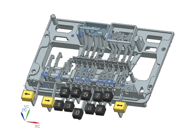
We disassembled the real machine down to the last screw, measured every component by hand, and reconstructed all 161 unique parts (of 500+ total) in Siemens NX. From those models we produced a complete digital assembly, exploded views, fully dimensioned engineering drawings, and a motion study of the mechanism in action.
Reverse-engineering a 500-part machine
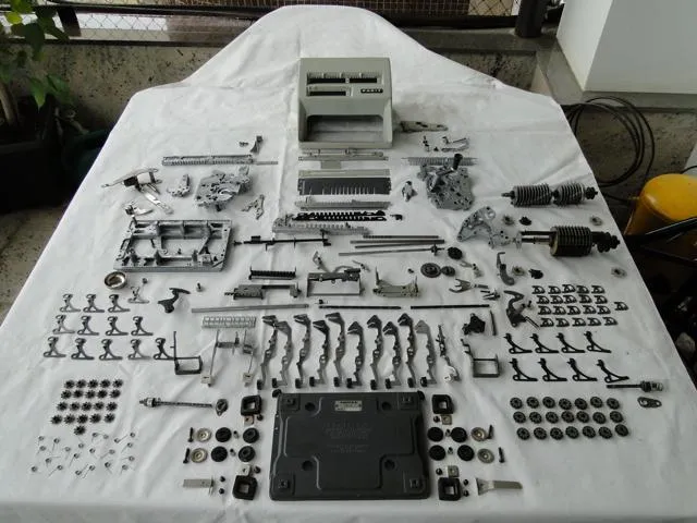
Disassembly alone was a project in itself. Parts were tightly packed, some were worn from decades of use, and a few were impossible to reach with calipers or a micrometer. Where we couldn’t measure directly, we improvised, tracing part outlines onto paper and using NX’s render image and scale body tools to recover true dimensions. Every model was then constrained into a master assembly using concentric and touch/align mates, with tolerances chosen to match each part’s real material and manufacturing process.
What I built
I owned the multiplication subsystem, the two parts that let the calculator multiply: the sliding quotient coupling and the rotor carriage. Across the project I modeled 29 unique parts and put in roughly 75 hours, the most of anyone on the team.
Sliding quotient coupling
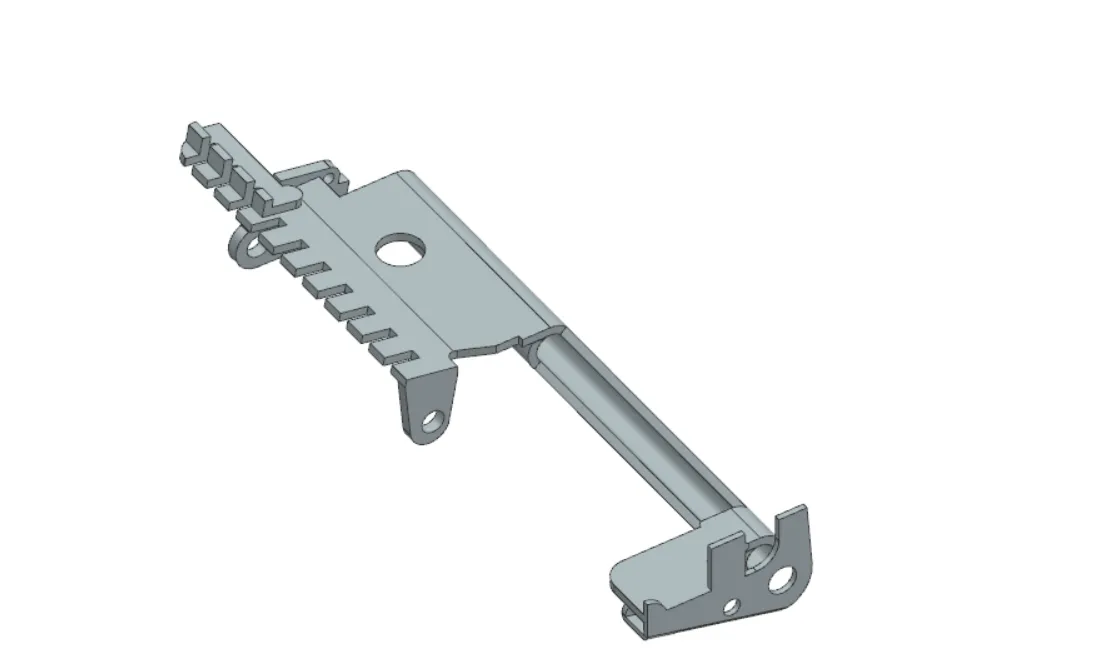
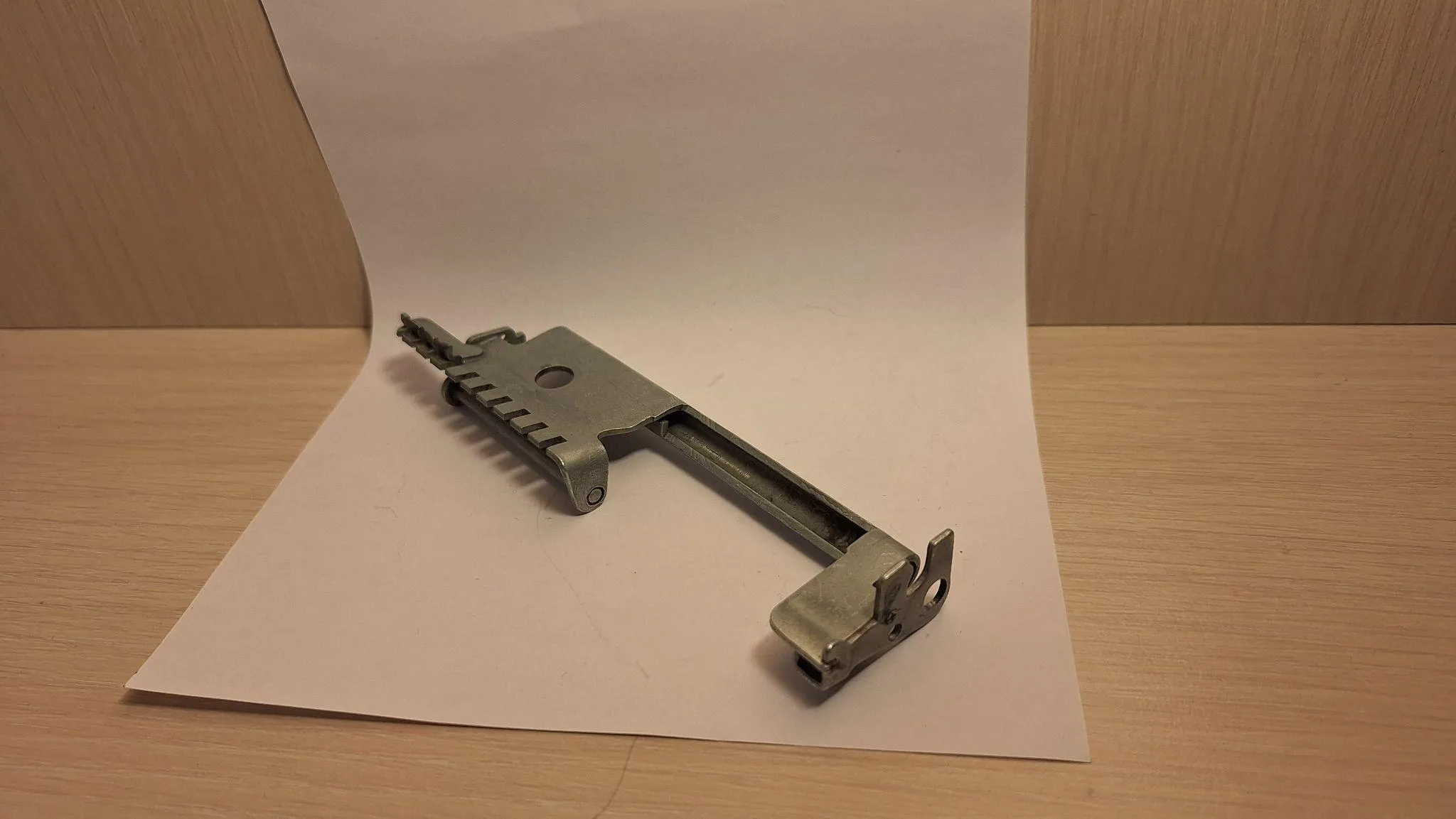
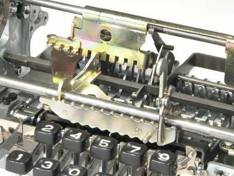
The sliding quotient coupling is what turns repeated addition into multiplication. As the first factor is entered, it slides laterally along the main shaft; when the operating arm is turned, a lever rotates the shaft and pushes the coupling forward, bringing its notches (the digits) into engagement with an arm on the rotor carriage. I modeled it in Siemens NX using datum planes and chamfers to match the real geometry, and assigned a sliding fit (H7/g6) so it moves freely along the shaft with minimal play and wear. In the real machine the part is built by rolling, band-sawing, sheet-metal folding, welding, and drilling, so the drawing had to respect what those processes can actually hold.
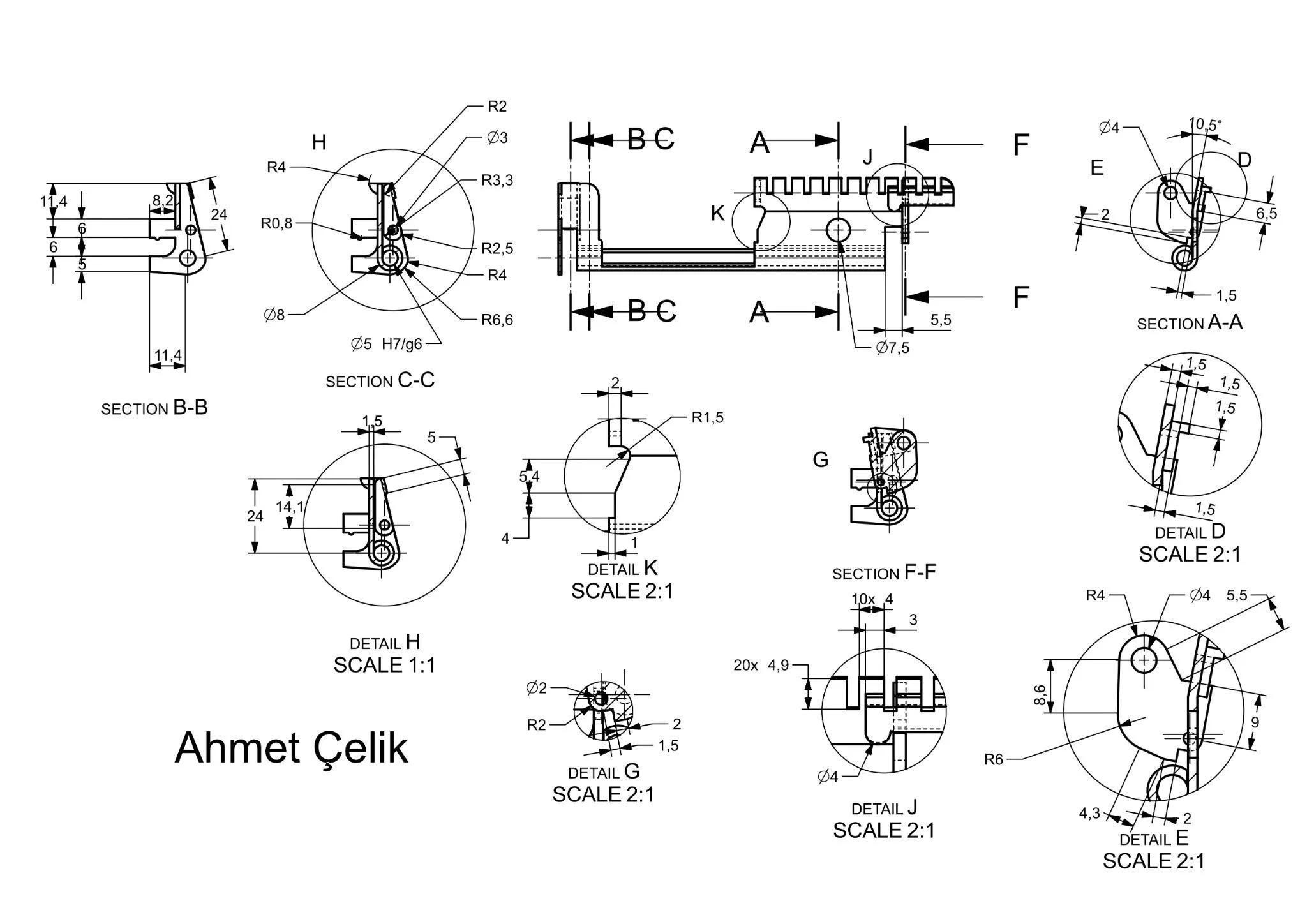
Rotor carriage
The rotor carriage is the other half of the mechanism. It rides along the shaft and engages the sliding quotient coupling, with a sliding hook on the carriage latching onto the front to keep everything stable through the motion. I built it using sweep and mirror operations, and toleranced the 7 mm steel shaft interface with a hole-based H7/n6 fit to stop the carriage drifting out of alignment under repeated use, with surface finishes tuned to reduce friction.
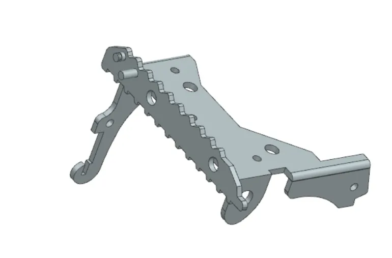
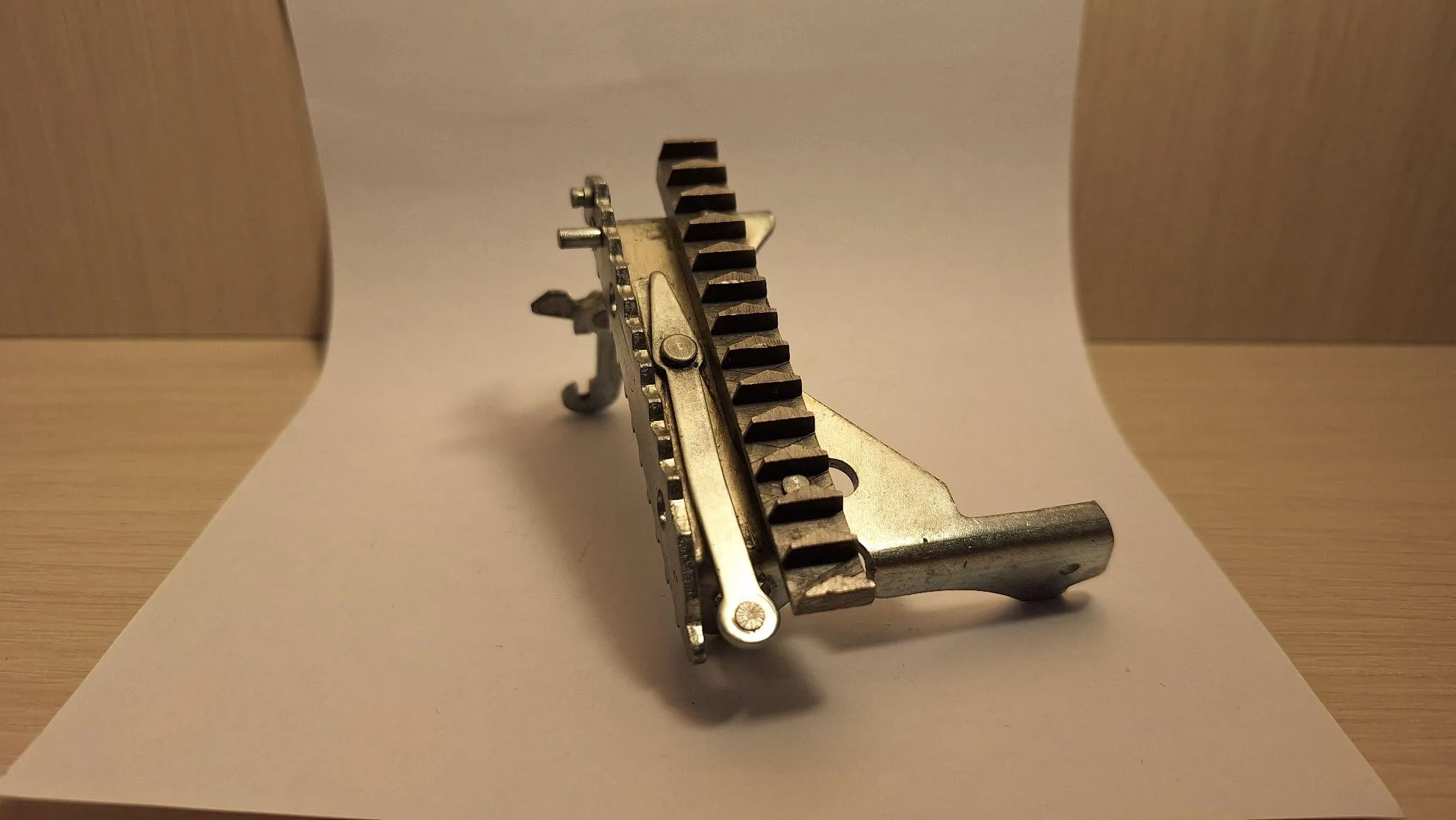
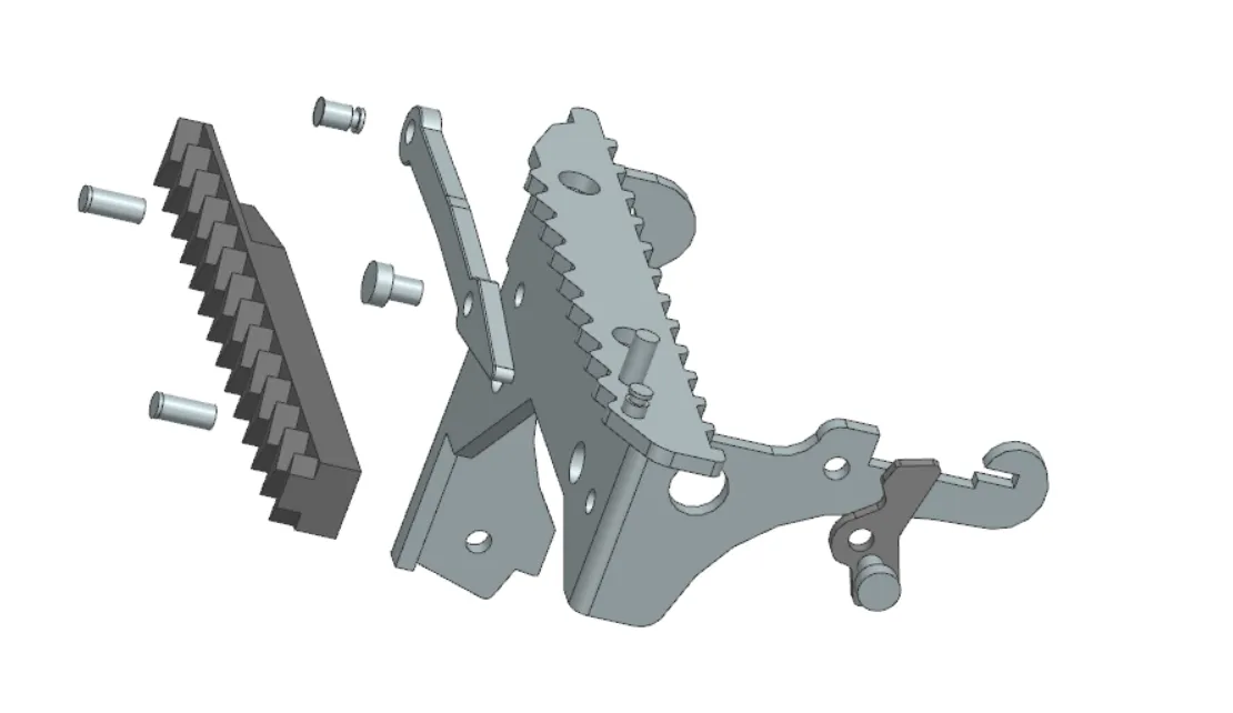
These two parts have to mesh precisely: a few hundredths of a millimetre off and the digits won’t engage cleanly. Seeing them sit correctly inside the real calculator, alongside the keys and rotor, was the payoff.
What I took away
This project taught me CAD as an engineering discipline, not just a drawing tool. A few things stuck:
- Tolerancing with intent. Choosing between H7/g6 and H7/n6 isn’t arbitrary: the fit has to follow the function (slide vs. stay put) and what the manufacturing process can actually hold. I came out genuinely comfortable specifying ISO limits and fits.
- Designing for assembly. My two parts only work in relation to the shaft, the coupling, and the carriage hook. Mating surfaces, clearances, and motion across parts mattered far more than perfecting any single component.
- Reverse-engineering from incomplete data. Real parts are worn, hidden, and hard to reach. Recovering accurate dimensions from a traced outline or a scaled render is a skill in itself.
- Manufacturing literacy. Modeling a folded-and-welded sheet-metal part forces you to understand how it’s actually made, which feeds straight back into how you draw and tolerance it.
More than anything, rebuilding a pre-digital machine with modern tools gave me real respect for how much engineering was packed into a calculator that runs on nothing but motion.