Whitworth Quick-Return Mechanism
A 3D-printed, stepper-driven Whitworth quick-return linkage that delivers a ~2.4× faster return stroke, validated against MATLAB and Siemens NX simulations.
- Siemens NX
- MATLAB
- Arduino
- 3D Printing
- Dynamics
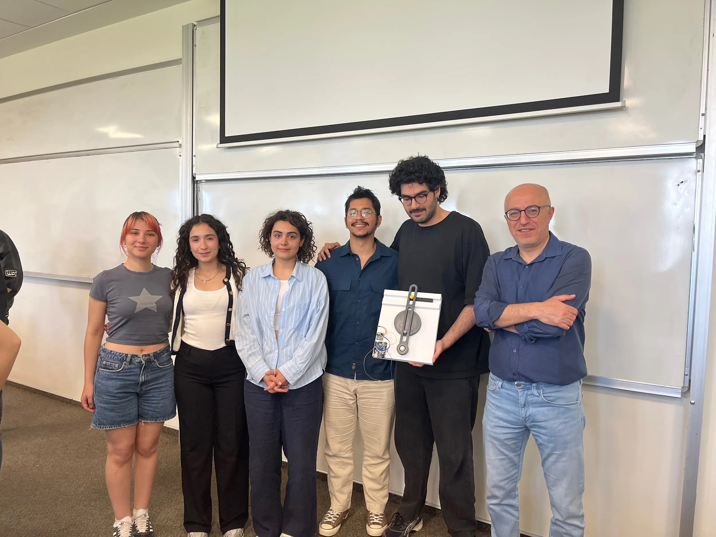
A team dynamics project for MECH 206 at Koç University: design, build, and analyze a Whitworth quick return mechanism, a single-degree-of-freedom linkage that turns steady rotary motion into a reciprocating stroke that is slow on the way out and fast on the way back. The result was a fully 3D-printed, motor-driven prototype whose measured motion was checked against both a Siemens NX motion simulation and a hand-derived MATLAB model.
What it does
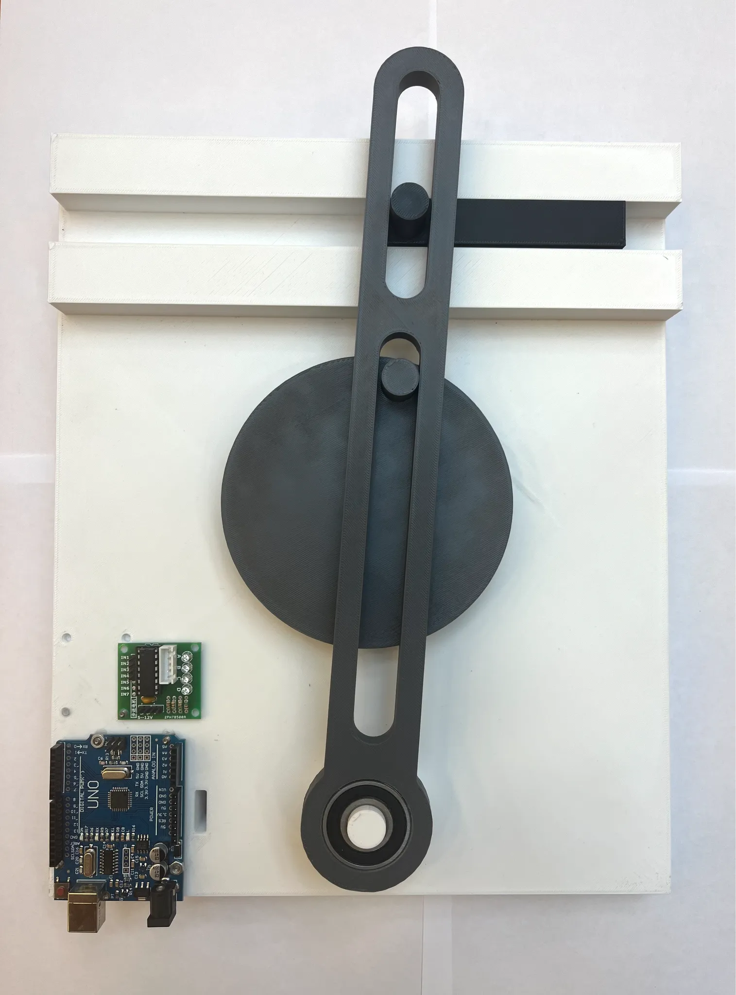
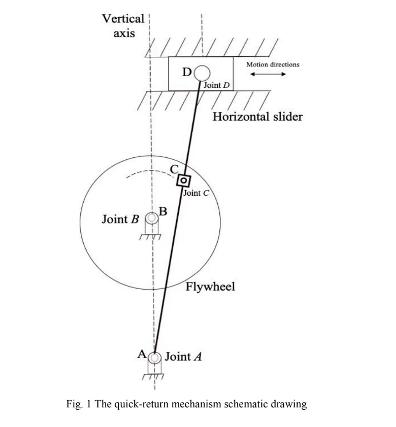
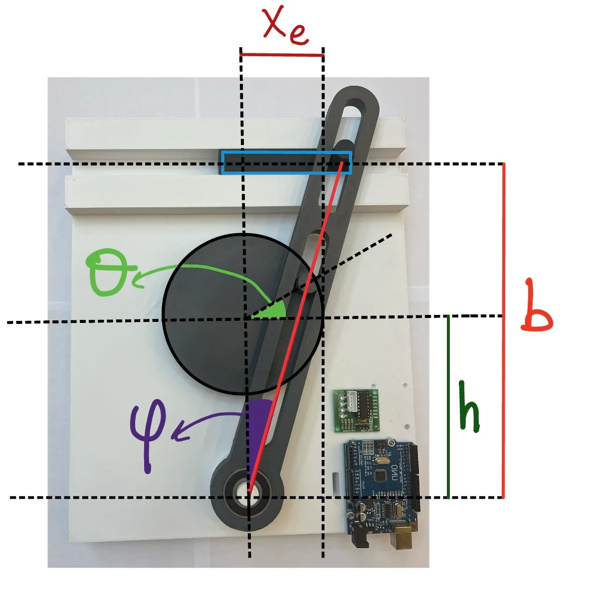
The Whitworth mechanism is the classic linkage behind shaping and slotting machines. A motor spins a crank at constant speed; the crank pin rides in the slot of a connecting lever, which drives a ram back and forth. Because the slot geometry sweeps the forward and return halves of the cycle through unequal crank angles, the tool moves slowly during the cutting stroke and quickly on the return, saving time without speeding up the cut. The whole system has one degree of freedom, so once the crank angle is fixed, every other position is determined.
Design
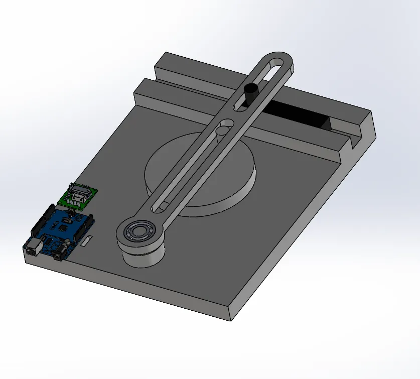
The full assembly was modeled in Siemens NX, with revolute joints for the crank and connecting lever and a slider joint for the ram. Touch-align constraints defined how surfaces interact as the crank drives the system, and motor-mount holes were sized directly in the platform to seat the physical stepper. During modeling we swept different crank radii in CAD to see how stroke length and return speed responded; this is what dialed in the quick-return effect.
Manufacturing
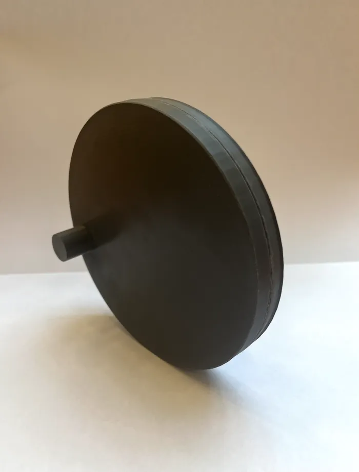
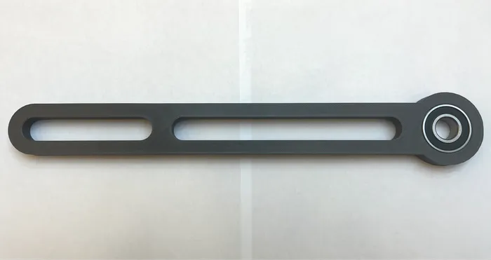
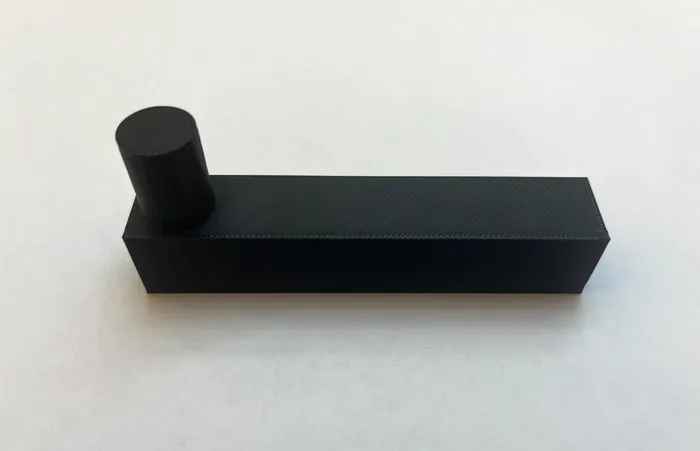
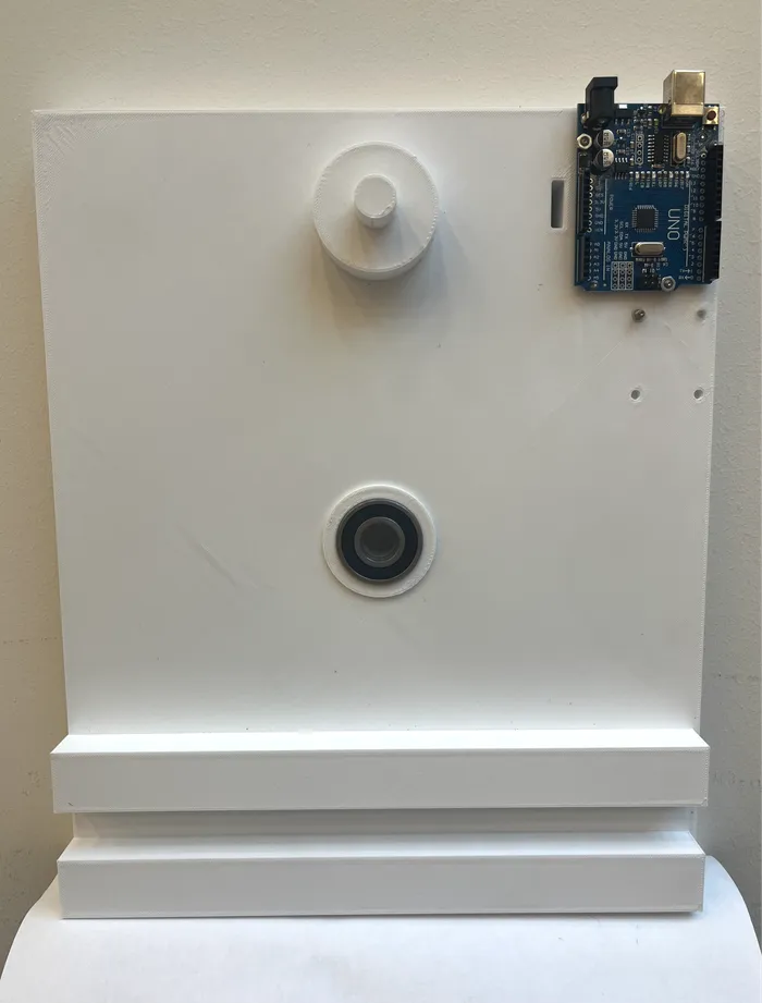
Every part was FDM 3D-printed in PLA (1.75 mm filament) with a gyroid infill. The gyroid’s continuous, curved cell walls give near-isotropic strength and spread mechanical stress evenly (no sharp internal transitions to concentrate load), which matters for the moving, load-bearing links while keeping weight and print time down. Tolerances were tuned so that 6202 ball bearings press-fit cleanly into their printed seats, which is what let the assembly run smoothly.
The four printed links that make up the mechanism:
Actuation and control
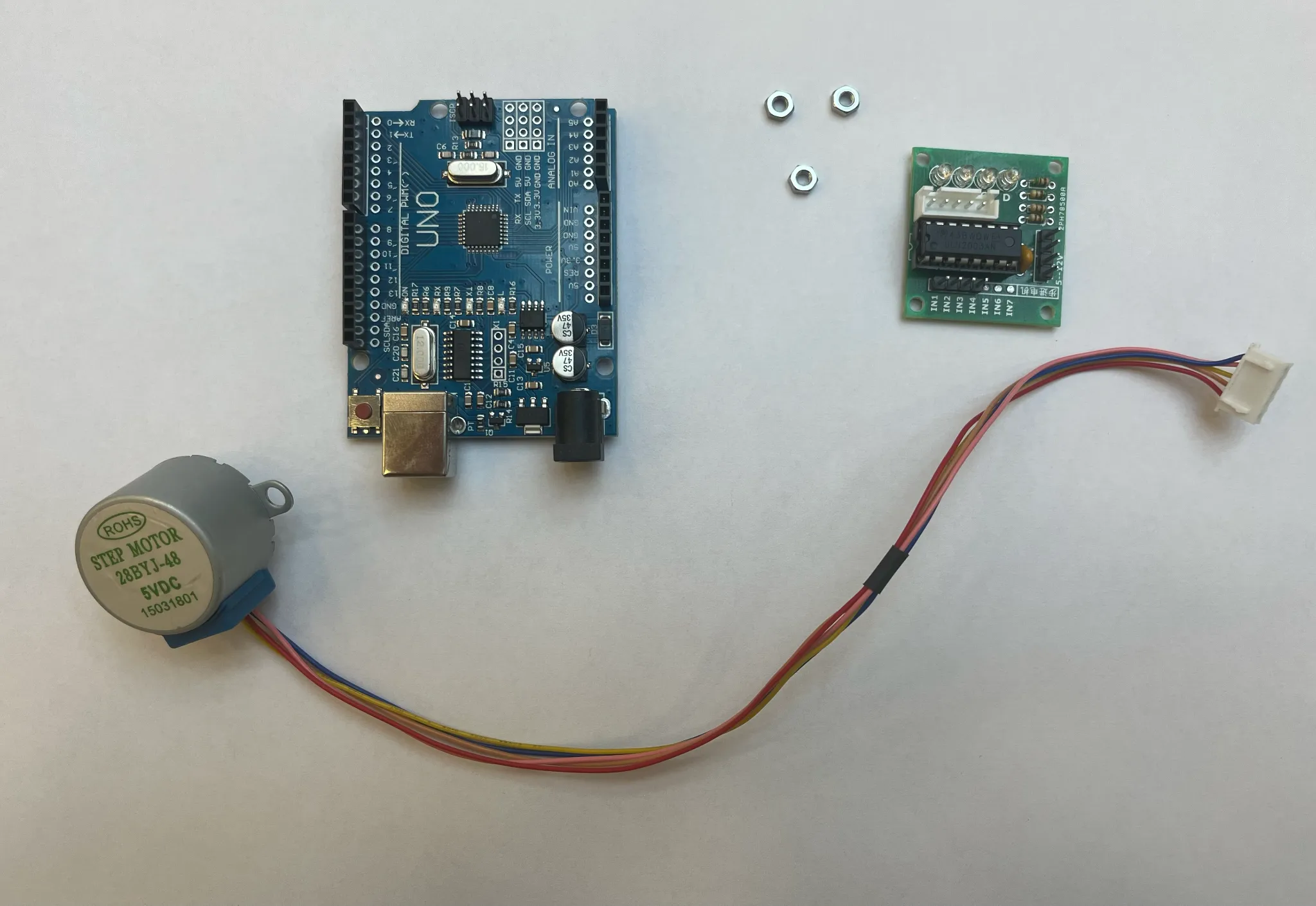
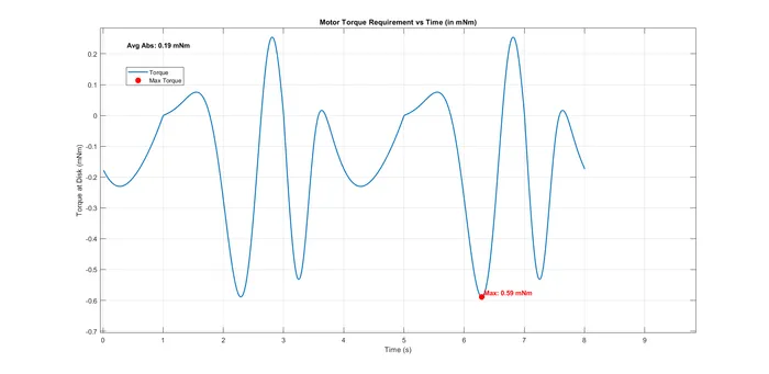
A 28BYJ-48 5 V stepper motor driven by a ULN2003 board and an Arduino Uno turns the crank at a constant 15 RPM (≈ 1.57 rad/s). A stepper was chosen specifically for its precise, repeatable speed and position control, which is what makes the quick-return asymmetry measurable. The required drive torque worked out to about 34.3 mN·m, enough for smooth, consistently-timed strokes.
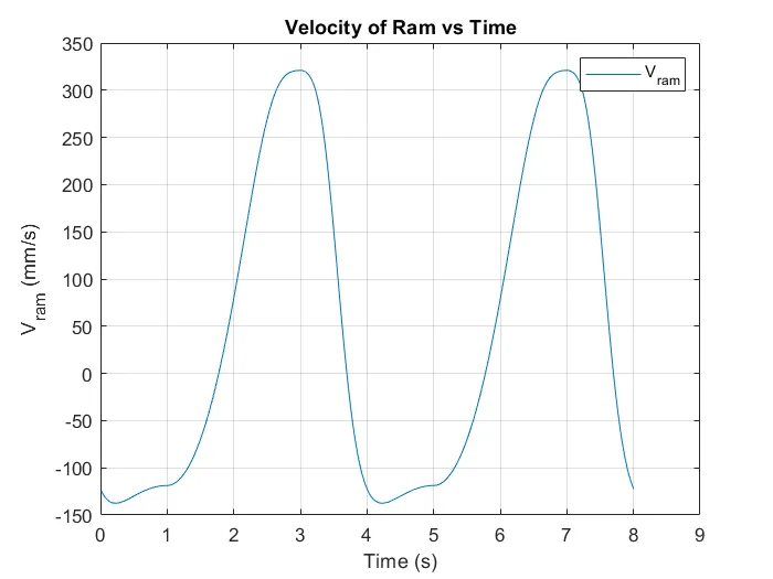
The asymmetry shows up directly in the numbers; the return stroke runs roughly 2.4× faster than the forward stroke:
Modeling and analysis
The motion was worked out three ways and cross-checked.
Kinematics. Positions were tied together with a vector-loop equation,
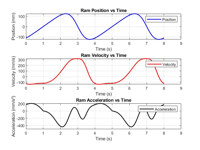
then differentiated for velocity and acceleration. Because the crank pin slides inside the rotating lever slot, the acceleration analysis carries a Coriolis term () from the rotating reference frame.

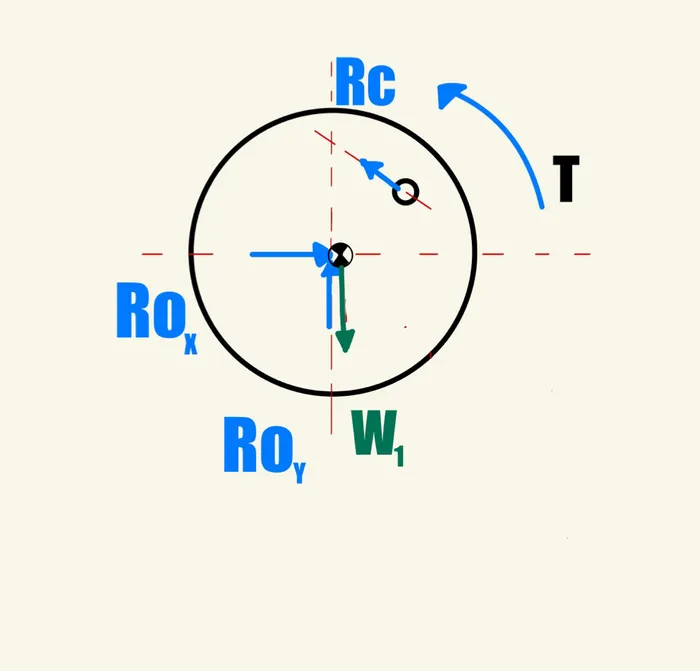
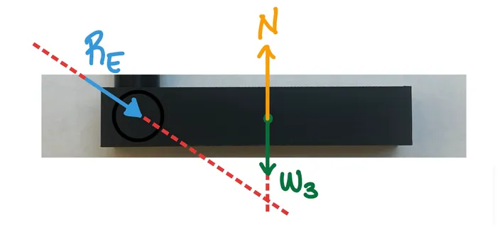
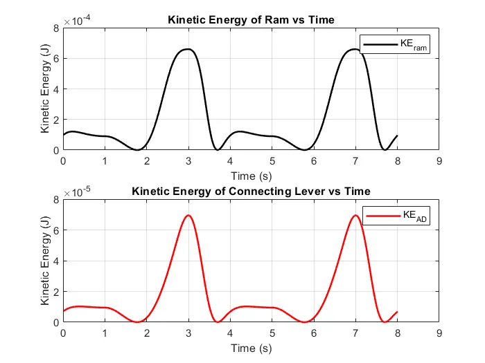
Kinetics. Free-body diagrams for the crank, connecting lever, and ram were built and solved with Newton’s second law. The crank rotates at constant speed, so its net moment is zero; the connecting lever, which does have angular acceleration, needed its moment of inertia computed (treating the crank as a disk, , with mass 73.1 g and radius 57.5 mm).
Results
An 8-second Siemens NX motion simulation (0.01 s steps, constant 1.57 rad/s), the MATLAB model built from the derived equations, and a MATLAB motion-tracking pass over video of the running prototype were all overlaid and compared. The curves line up on the quick-return signature (a long, gentle forward stroke and a short, sharp return), and the crank’s kinetic energy stays flat, as expected for constant angular velocity. Remaining gaps trace back to mechanical tolerances and backlash, unmodeled friction, tracking noise, and the rigid-link assumption.
My contributions
This was a five-person team project; within it, I owned:
- Project framing: the introduction, working principle, and real-world context (shaping and slotting machines).
- Motor torque analysis: determining the ~34.3 mN·m drive torque needed for smooth, consistently-timed strokes.
- MATLAB trajectory simulation: animating the ram’s motion over a full cycle and confirming the slow-forward / quick-return behavior matched the theoretical kinematics.
- Planar kinematics derivation: contributing to the position, velocity, and acceleration vector-loop analysis.
- Experimental validation: leading the comparison of the physical mechanism’s tracked motion against the theory and the NX simulation.
What I learned
- The full design-to-manufacturing pipeline: idea → Siemens NX CAD → functional 3D-printed prototype.
- FDM printing in practice: gyroid infill for a strong, light part, and the tolerancing needed for press-fit bearing seats.
- Embedded motor control: programming an Arduino to drive a stepper at a steady, known speed.
- MATLAB as an analysis tool: kinematic, dynamic, and energy plots plus video-based motion tracking.
- Reconciling theory with reality: quantifying where a clean rigid-body model diverges from a real, printed mechanism, and why.
- Integrating mechanical and electronic subsystems into one working device.
Details
- Course: MECH 206, Dynamics, Koç University
- Type: Team term project (5 members)
- Tools: Siemens NX, MATLAB, Arduino, FDM 3D printing
- Hardware: 28BYJ-48 stepper · ULN2003 driver · Arduino Uno · 6202 bearings · PLA
- Date: June 2025